
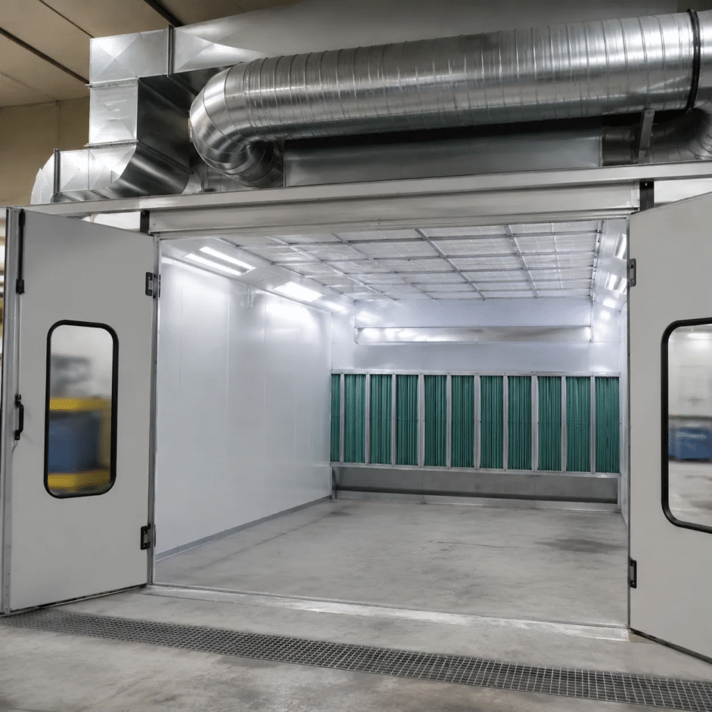
The Core Metrics of Spray Booth Ventilation
Designing an effective spray booth requires precise control over air movement. If your ventilation system isn’t dialed in, you risk poor finish quality, hazardous overspray buildup, and regulatory compliance failures. Getting this right comes down to mastering three core metrics: airflow volume, air velocity, and static pressure resistance.
Page URL: https://sprayboothmanufacturer.com/product/
Understanding Airflow Volume (CFM) & Velocity (FPM)
To keep a finishing cabin safe and clean, air must move through the space at a controlled, continuous rate.
- Airflow Volume (CFM): Measured in Cubic Feet per Minute, CFM represents the total volume of air your exhaust fan moves out of the cabin every 60 seconds.
- Face Velocity (FPM): Measured in Feet per Minute, FPM represents the speed at which that air travels across the open face or cross-section of the booth.
For standard industrial ventilation design, maintaining the correct face velocity FPM is non-negotiable. Industry safety thresholds generally dictate a minimum velocity of 100 FPM for crossdraft booths and 50 to 100 FPM for downdraft configurations to effectively pull overspray away from the operator’s breathing zone and into the overspray filtration system.
The Math Behind the Airflow: Calculating Booth CFM
Calculating the exact airflow required for your cabin dimensions is a straightforward formula. You must determine the cross-sectional area through which the air flows and multiply it by your target velocity.
For a standard crossdraft booth, the air moves horizontally from wall to wall. The calculation uses the width and height of the cabin:
$Required CFM = Width × Height × Target Velocity (FPM)$
For a downdraft booth, the air moves vertically from ceiling to floor. The calculation shifts to use the length and width of the cabin footprint:
$Required CFM = Length × Width × Target Velocity (FPM)$
| Booth Type | Dimension Variables | Target Velocity | Example Calculation (14’W x 9’H x 24’L) |
|---|---|---|---|
| Crossdraft | Width x Height | 100 FPM | $14 \times 9 \times 100 = \textbf{12,600 CFM}$ |
| Downdraft | Length x Width | 60 FPM | $24 \times 14 \times 60 = \textbf{20,160 CFM}$ |
Using an accurate paint booth CFM calculator approach ensures you do not undersize your fan, which causes hazy cabins, or oversize it, which needlessly increases equipment and energy costs.
Demystifying Static Pressure and Ductwork Resistance
A fan does not operate in a vacuum. It must push air through filters, intake plenums, and exhaust stacks. This resistance against the moving air is called static pressure ventilation ductwork resistance, measured in inches of water column (W.C.).
Every component in the airflow path adds to this resistance: Dry Filters: Clean exhaust and intake filters offer minimal resistance, but as they load with paint overspray, static pressure rises significantly. Ductwork Runs: Straight duct runs create friction. Every foot of pipe adds to the total system resistance. Elbows and Transitions: Sharp turns disrupt airflow. A single 90-degree elbow can add as much resistance as 30 feet of straight pipe, expanding the overall ductwork equivalent straight length.
When selecting a fan, referencing the bare CFM requirement is not enough. You must select a fan rated to deliver that target CFM at the specific total static pressure your entire duct and filter system generates when the filters are dirty. Ignoring static pressure leads to severe airflow drops right when you need performance the most.
Airflow Direction: Selecting the Right Configuration
Choosing how air moves through your cabin determines your final finish quality and daily operating costs. You need to match the cabin mechanics to your specific shop footprint and production goals.
Crossdraft Systems: Front-to-Back Airflow
Crossdraft configurations pull air directly from the shop floor through filters in the intake doors, moving it horizontally across the vehicle or part, and exhausting it out the back back wall.
- The Pros: Lowest upfront installation cost and easiest setup since it requires no concrete pit excavation or raised basement flooring.
- The Cons: Because the air travels horizontally, overspray from the front of the vehicle can drift over the back sections. Painters must plan their spraying sequence carefully to avoid dry spray and airborne contaminants.
Downdraft Systems: Premium Gravity-Assisted Quality
For top-tier finish quality, a downdraft vs crossdraft comparison always highlights downdraft as the gold standard. Air enters through a full-length ceiling intake plenum airflow system and is pulled straight down into a filtered floor pit or a raised exhaust basement.
- Gravity Assistance: This system pulls overspray and airborne dust straight down toward the floor, away from the painter’s breathing zone and the freshly painted surfaces.
- Finish Quality: Minimizes buffing and correction time, making it the preferred setup for high-end automotive and industrial finishes.
Semi-Downdraft & Side-Downdraft Systems
These mid-tier solutions offer an excellent balance of performance and budget when a concrete pit isn’t an option.
| System Type | Airflow Path | Best Used For |
|---|---|---|
| Semi-Downdraft | Introduces air through the ceiling at the front of the booth, pulling it diagonally down and out through the rear exhaust wall. | Shops wanting better clearing speed than a crossdraft without cutting concrete. |
| Side-Downdraft | Brings air down through a full ceiling plenum and exhausts it horizontally through low-profile side wall filters. | Facilities with high-volume production schedules that cannot install an in-ground pit. |
Tailoring AUTOKE Systems to Your Production Goals
At AUTOKE, we engineer our ventilation configurations to match the exact output demands of global industrial and automotive facilities. We look at your daily part volume, coating types, and shop layout to integrate the right overspray filtration system with the ideal cabin footprint. Whether your shop requires a high-velocity downdraft line to maximize throughput or a space-saving side-downdraft setup to keep installation overhead low, we design the airflow to protect your painters and eliminate finish contamination.
Spray Booth Exhaust Fan Placement and Selection
Choosing and positioning your exhaust fan isn’t just about moving air—it is about overcoming resistance and keeping your shop safe. If you pair the wrong fan with heavy ductwork, your airflow drops, overspray settles, and your finish quality takes a hit. We design our systems to balance raw power with smart placement to keep your booth running efficiently.
Axial vs. Centrifugal Fans
Different booth layouts require different fan types depending on the static pressure ventilation ductwork resistance they must overcome.
| Fan Type | Best Used For | Key Advantage |
|---|---|---|
| Tube Axial Fans | Crossdraft and short duct runs | High volume airflow with low static pressure resistance. |
| Centrifugal Fans | Downdraft systems and long, complex ducting | High static pressure capability; pulls air efficiently through dense overspray filtration systems. |
Strategic Fan Placement and Building Dynamics
Where we place the fan matters just as much as the fan type itself. Proper spray booth exhaust fan placement works with gravity and the natural flow of your shop’s building envelope.
- Exhaust at the Lowest Point: For downdraft and side-downdraft setups, pulling air low to the ground works with gravity to draw overspray away from the painter’s breathing zone immediately.
- Minimize Duct Bends: Every elbow adds to the ductwork equivalent straight length, increasing resistance. We position fans to ensure the straightest path out of the building.
- Weather Protection: Roof-mounted fans must use reliable butterfly dampers or weather caps to prevent backdrafts without choking your exhaust volume.
Critical Safety Factors and Compliance
When dealing with atomized paints and solvent vapors, spark prevention is non-negotiable. We build our ventilation systems around strict safety frameworks to eliminate ignition risks.
- Explosion-Proof Motors: All exhaust fan motors must be totally enclosed and rated for Class I, Division 1 hazardous locations to isolate electrical components from flammable fumes.
- Non-Sparking Fan Impellers: We utilize aluminum or specialized composite fan blades. If a component ever shifts, a non-sparking fan impeller ensures that metal-on-metal contact won’t create a catastrophic spark inside the duct.
Mastering Booth Pressure: Positive vs. Negative Cabin Dynamics
Controlling the air pressure inside your cabin is the secret to a flawless finish. When designing a spray booth ventilation design, the balance between the air coming in and the air being exhausted dictates whether your shop stays clean or becomes a magnet for dust.
The Industry Ideal: Balanced or Slightly Positive Pressure
We always aim for a positive pressure paint booth or a perfectly balanced system. When your intake airflow slightly exceeds the exhaust airflow, the cabin balloons with clean air. If there are any minor gaps in the door seals or structure, air pushes out of the booth rather than sucking contaminants in.
| Pressure Type | Airflow Dynamics | Impact on Paint Quality |
|---|---|---|
| Positive Pressure | Intake CFM > Exhaust CFM | Pushes air out of seals; locks out dust and debris. |
| Negative Pressure | Exhaust CFM > Intake CFM | Sucks shop air, lint, and dirt through every tiny crack. |
| Balanced System | Intake CFM = Exhaust CFM | Ideal neutral state; requires precise mechanical calibration. |
The Danger of Negative Cabin Pressure
Operating under negative cabin pressure triggers a destructive vacuum effect. The moment your exhaust fan pulls harder than your intake plenum can supply, the booth pulls dirty shop air through door gaskets, floor drains, and seams. This unfiltered air lands directly on your wet clear coats, leading to hours of unnecessary color sanding and buffing.
Monitoring Systems and Magnehelic Gauges
You cannot manage what you do not measure. We install a Magnehelic pressure gauge on every cabin to track differential pressure. This tool compares the pressure inside the booth against the pressure of the outside shop floor.
- Green Zone (0.02 to 0.05 inches of water column): Indicates an optimal, slightly positive cabin environment.
- Negative Readings: Signifies a starved intake or clogged intake filters.
- Excessive Positive Pressure: Indicates heavily loaded exhaust filters that require immediate replacement.
The Role of Air Make-up Units (AMUs)
An air make-up unit (AMU) is the ultimate tool for automatic pressure management. Instead of manually adjusting dampers as your overspray filtration system loads up with paint, an AMU automatically ramps fan speeds up or down. It replaces the exact volume of air being exhausted, heating the incoming air to the correct temperature while maintaining a flawless, balanced pressure profile automatically.
NFPA 33 and OSHA Spray Booth Ventilation Compliance
When designing an industrial ventilation design, meeting federal safety standards isn’t optional—it keeps your shop legal and your team safe. We build our systems to align directly with OSHA mandates and NFPA 33 spray booth requirements to handle hazardous vapors and combustible overspray.
OSHA Face Velocity & Worker Breathing Zone Thresholds
OSHA focuses heavily on health and air quality in the worker breathing zone. To keep operators from inhaling toxic fumes, the ventilation system must maintain a strict face velocity FPM (Feet Per Minute) across the open face or filters of the booth.
- Continuous Airflow: The system must constantly pull overspray away from the painter’s breathing zone.
- Minimum Velocity: Maintaining the correct FPM ensures hazardous vapors are instantly captured and routed to the exhaust filtration system.
- Airflow Monitoring: Regular testing is required to prove the booth meets these thresholds during operation.
NFPA 33 Fire Prevention & Electrical Safety
While OSHA protects the worker’s lungs, NFPA 33 prevents the shop from catching fire. Spraying flammable coatings creates a Class I, Division 1 electrical environment inside the cabin and exhaust ductwork.
- Explosion Isolation: All motors and lighting fixtures inside the booth or exhaust stream must be explosion-proof.
- Non-Sparking Mechanicals: Exhaust fans must utilize non-sparking fan impellers (typically aluminum or brass) to prevent friction sparks if a component shifts.
- Clearance Distions: Clear separation distances must be maintained between the spray booth structure and any open flame or ignition sources.
Quick Compliance Reference
| Regulatory Body | Core Focus Area | Key Technical Requirement |
|---|---|---|
| OSHA Mandates | Worker Health & Safety | Minimum face velocity FPM thresholds in the breathing zone |
| NFPA 33 Standards | Fire & Explosion Prevention | Class I, Div 1 electrical ratings & non-sparking fan impellers |
| Environmental (EPA) | Emissions Control | High-efficiency overspray filtration system capture efficiency |
Frequently Asked Questions: Spray Booth Ventilation Design Basics
How do you calculate spray booth CFM requirements?
To find your target airflow volume, we look at the cross-sectional area of the booth perpendicular to the airflow direction and multiply it by the required face velocity FPM (feet per minute).
| Booth Type | Calculation Formula | Standard Target Velocity |
|---|---|---|
| Crossdraft | Width × Height × Face Velocity | 100 FPM |
| Downdraft | Width × Length × Face Velocity | 50–100 FPM |
For example, using a paint booth CFM calculator approach for a crossdraft cabin that is 14 feet wide and 9 feet high: 14 × 9 = 126 sq. ft. area. 126 sq. ft. × 100 FPM = 12,600 CFM required. Note: Always size your exhaust fan to hit this CFM while accounting for the static pressure resistance of your filters and ductwork.
What is the difference between positive and negative pressure in a paint booth?
Cabin pressure dictates your finish quality and shop safety. Maintaining the right balance prevents contamination and keeps hazardous fumes contained.
- Positive Pressure Paint Booth: We introduce slightly more clean air through the intake plenum airflow than the exhaust fan pulls out. This forces air out of small cabin cracks, preventing shop dust from entering.
- Negative Cabin Pressure: The exhaust fan pulls out more air than the intake supplies. This creates a vacuum effect. If you need negative cabin pressure troubleshooting, look for sealed doors pulling inward, which sucks ambient shop dust under seals and ruins clear coats.
Why is fan placement critical for safety and compliance?
Proper spray booth exhaust fan placement ensures hazardous vapors are moved away from the worker’s breathing zone immediately while minimizing fire risks.
- Vapor Management: Overspray and solvent vapors are heavier than air. Fans must be placed strategically to pull these vapors down and away seamlessly.
- NFPA 33 Spray Booth Requirements: The fan and motor assembly must comply with strict fire codes. This means utilizing non-sparking fan impellers (typically aluminum) and explosion-proof motors to eliminate any ignition sources within the exhaust stream.
- Ductwork Efficiency: Placing the fan correctly minimizes bends in the exhaust stack, reducing the ductwork equivalent straight length and keeping static pressure low.
Related Sources
- https://www.aivc.org/sites/default/files/airbase_4732.pdf
- https://www.cdc.gov/niosh/surveyreports/pdfs/329-12a
- https://www.paint.org/wp-content/uploads/2021/09/Papasavva_Feb02.pdf
- Bus Spray Booth Design Guide → https://sprayboothmanufacturer.com/transit-coach-spray-booth-requirements/
- Truck Paint Booth Guide → https://sprayboothmanufacturer.com/truck-paint-booth-semi-truck-spray-booth-specifications-buying-guide/
- Other related products → https://www.autokemanufacture.com/product
- Contact our sales Team → https://sprayboothmanufacturer.com/contact-us/
✅ CE Certified | ✅ ISO 9001:2015 | ✅ Factory Direct | ✅ Ships to 60+ Countries | ✅ 1-Year Warranty | 🔒 HTTPS Secured